
- Details
- Last Updated on Monday, 01 December 2014 15:43
 Sedimentation Equation (Article)
Jiri Brezina
Brezina, Jiri, 1979b, Particle size and settling rate distributions of sand-sized materials: 2nd European Symposium on Particle Characterisation (PARTEC), Nürnberg, West Germany,
ABSTRACT: The author had been assembling the sedimentation data including particle shape since 1960. All of the important influences could be defined in terms of an equation for the sedimentation drag coefficient as a function of Reynolds' number and Shape Factor, CD = f (Re, SF). Because the Sedimentation velocity of a single grain is the most accurate measure of grain size, the sedimentation equation is the basis for any sedimentation grain size analyzer such as MacroGranometer™, the advanced settling tube system extending the single grain accuracy to particle collectives.
DRAG COEFFICIENT as FUNCTION OF REYNOLDS’ NUMBER
and SHAPE of IRREGULAR PARTICLE
For smooth spheres, many equations have been proposed for the drag coefficient as function of Reynolds' number. Most of them can be expressed in form of a polynomial as shown in TABLE 1.
Parameters of polynomial equations for drag coefficient CD of sedimenting spheres as function of Reynolds’ number Re. Equations by KOMAR et al. (1978) are given for comparison (they are not valid for spheres).
Validity limits are approximate.
CD = A.Rea + B.Reb + C.Rec + D.Red + E.Ree + F.Ref
|
Authors |
Year |
a |
A |
b |
B |
c |
C |
d |
D |
e |
E |
f |
F |
Re minimum |
Re |
|||||
|
NEWTON |
1687 |
|
|
|
|
0 |
(0.44) |
|
|
|
|
|
|
103 |
2.105 |
|||||
|
STOKES |
1845 |
-1 |
24 |
|
|
|
|
|
|
|
|
|
|
10-7 |
10-1 |
|||||
|
KOMAR Eq. et 12 al., Eq. 13 |
1978 |
-1 |
22.704 23.928 2.16 |
|
|
|
|
given for SF’=1 valid: 0.4<SF’<0.8 |
10-7 |
2 |
||||||||||
|
OSEEN |
1910 1929 |
-1 |
24 |
|
|
0 |
4.5 4.5 |
1 |
-0.35625 |
2 |
0.0832 |
3 |
-0.0210512 |
10-7 |
1 |
|||||
|
SCHILLER |
1933 1934 1959 |
-1 |
24 |
-0.313 |
3.6 |
|
|
valid for Stokes’ Reynolds' number |
10-7 |
8.102 |
||||||||||
|
0.38 |
0.0624 |
|
|
|
|
|||||||||||||||
|
RUBEY |
1933 1943 1969 1971 1974 |
-1 |
24 |
|
|
0 |
2 |
derived for non-spherical particles |
10-7 |
2.10 |
||||||||||
|
KÜRTEN et al. KASKAS |
1966 1964 |
-1 |
21 |
-0.5 |
6 |
0 |
0.28 0.4 |
|
|
10-7 |
104 |
|||||||||
|
BREZINA |
1979 |
-1 |
23.963 |
-0.5 |
4.058 |
0 |
0.37965 |
for SF’1.2; valid: 0.1≤SF’<1.2 |
10-7 |
104 |
||||||||||
For irregular particles, most experimental data on drag coefficient, Reynolds’ number and Corey's Shape Factor have been compiled by SCHULZ, WILDE and ALBERTSON (1954). COLBY and CHRISTENSEN (1957) disclosed inconsistency in the drag coefficient definition and experimental terms of some data of SCHULZ et al., and constructed an improved the best fit plot of the drag coefficient logarithm as function of the Reynolds’ number logarithm (Nikuradze diagram) for various SF’ values.
In order to express the available data on irregular particles mathematically, BREZINA (1977) extended the equation of KASKAS (1964, 1970) by adding the SF’ shape as a third variable to each term of the polynomial:
CD = A Re-1 + B Re-0.5 + C [Re < 104 ] (1) .
In this paper, the parameters of the equation are slightly modified in order to fit the recent experimental data of KOMAR and REIMERS (1978), which reveal a much stronger influence of particle shape onto the drag coefficient under low Reynolds' numbers than assumed earlie
|
|
|
for SF’ = |
||
|
|
|
1.2 |
1.0 |
0.3 |
|
A |
P2 SF’P1 |
23.963 |
24.66 |
29.80 |
|
B |
P4 SF’P3 |
4.058 |
4.07 |
4.15 |
|
C |
P6SF’P5 |
0.37967 |
0.49 |
2.64 |
The parameters P1 through P6 are defined by the following values:
|
P1 = -0.1572509737 |
P3 = -0.0161675868 |
P5 = -1.398809673 |
|
P2 = 24.66 |
P4 = 4.07 |
P6 = 0.49 |
The plot of the equation (1) in the Nikuradze diagram is shown on the FIG. 2 with two systems of parallel straight lines of particle size and settling rate, valid for quartz sedimenting in water under standard conditions. One system represents PHI particle size, the other PSI settling rate
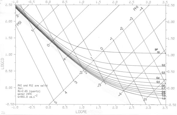
FIG 2: Drag coefficient (logCD) as function of Reynolds’ number (logRe) for various Hydraulic Shape Factor (SF’) values in Nikuradze diagram according to eq. (1); the additional variables PHI-particle size and PSI-settling rate are plotted too as diagonal coordinates. Valid for naturally worn quartz particles sedimenting in distilled water 24°C, gravity acceleration G = 981 cm/sec2 .
(see page 9 for PHI and PSI notations). FIG. 3 reveals a three-dimensional view of the eq. 1; a vertical view (map) in contour (iso)lines is shown in FIG. 4.
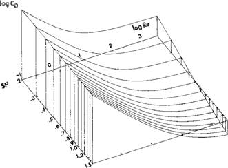
FIG. 3: Drag coefficient (logCD) as function of Reynolds’ number (logRe) and Hydraulic Shape Factor (logSF’); naturally worn sedimenting particles; calculated from the equation (1).
Comparison of some eq. (1) CD values with those by various authors is given in TABLE 2.
|
|
(1) |
(2) |
(3) |
(4) |
(5) |
(6) |
(7) |
(8) |
|
logRe |
log CD |
log CDKASKAS |
Difference |
log CD |
log CDCOLBY |
logCD |
Difference |
|
|
(4) - (5) |
(4) - (6) |
|||||||
|
-3 |
4.3819 3.3869 |
4.3825 |
-,0006 |
4.4762 3.4806 |
|
|
|
|
|
-1 |
2.4029 1.4533 |
2.4032 |
-.0003 +.0000 |
2.4966 1.5634 |
2.415 |
2.537 |
+.082 |
-.040 |
|
1 |
0.6084 0.0108 |
0.6091 |
-.0007 |
0.8409 0.5254 |
0.860 |
|
-.019 |
|
|
3 |
- 0.2741 |
-.2592 |
-.0149 |
0.4473 0.4289 |
0.441 |
|
+.006 |
|
TABLE 2
Data refer to:
column (1): eq. (1), SF’=1.2 (smooth spheres) of this paper;
column (2): KASKAS (1964);
column (4): eq. (1), SF’=0.3 (flat particles) of this paper;
column (5): COLBY + CHRISTENSEN (1956) SF’=0.3 (flat particles);
column (6): KOMAR + REIMERS (1978) SF’=0.3 (flat particles).
SF
log Re
FIG. 4: Contours of drag coefficient (log CD) in terms of Reynolds' number (logRe) and Hydraulic Shape Factor (SF’). Calculated from the eq. 1 using parameters of BREZINA (1977) Naturally worn sedimenting particles.
The drag coefficient values for SF’=1.2 approach very closely those for smooth spheres defined by KASKAS (1964), and even closer experimental data in the range 3<logRe<4. A satisfactory agreement for SF’= 0.3 with the data of COLBY and CHRISTENSEN (1957) and with the equation (14) of KOMAR and REIMERS (1978) is evident (Table 2).
While the Corey's Shape Factor is defined by three particle dimensions only, and the experimental data resulted from studies on naturally worn particles,the smooth spheres have a smaller drag coefficient value than naturally worn irregular particles with SF=1.0 (isometrical particles). This smaller drag coefficient value corresponds to SF’ = 1.2 from the eq. (1). Logically, there is a strong difference between an actually measured SF and the Hydraulic Shape Factor SF’ defined by the regression equation (see page 3).
LOGARITHMIC NOTATIONS OF PARTICLE SIZE (PHI) and SETTLING RATE (PSI).
Retaining the geometric grade scale of J. A. UDDEN (1898), W. C. KRUMBEIN (1934) introduced binary logarithm of particle size, PHI (transcription of the Greek letter φ), which became popular among geologists because it makes calculations and expressions easy. G. V. MIDDLETON (1967) applied the binary logarithm to settling rate, and defined PSI (transcription of the Greek letter ψ):
PHI = -log2Xi , (2a)
inversely Xi = 2-PHI ; (2b)
PSI = -log2Yi , (3a)
inversely Yi = 2-PSI . (3b)
log2 is a logarithm to the base 2 (=binary logarithm);
Xi is a dimensionless ratio of a given particle size, di, in millimeters, to the standard particle size of 1 millimeter, d0 (=di/d0; D. A. McMANUS, 1963; W. C. KRUMBEIN, 1964);
Yi is a dimensionless ratio of a given settling rate, vi, in centimeters per second, to the standard settling rate of 1 centimeter per second, v0 (=vi/v0).
PARTICLE SIZE AND SETTLING RATE EQUATIONS. When rewriting the equation (1), an equation for settling rate v (in centimeters per second) can be written:
K v-2 + L v-1 + M v-0.5 + C = 0 , (4)
if v = X-2 ,
then: K X4 + L X2 + M X + C = 0 .
K = -2-PHI(Rs-Rf) G/Rf . 7.5 ,
L = 10 A . n . 2PHI ,
M = B . (10n)0.5 . 20.5PHI ,
in which:
Rs is the specific gravity of the solid (Rs of quartz is 2.65),
Rf is the specific gravity of the fluid;
Rf of the distilled water varies with temperature; within the temperature range
15°C through 30°C, the following equation has been found satisfactory:
Rfw = a . tb , (5)
in which
Rfw is specific gravity of distilled water under temperature t in ° C (centigrades),
a = 1.013176326
b = -0.0049852
n is kinematic viscosity of the fluid in stokes.
The following equation for the kinematic viscosity of distilled water, developed by Dr. R. E. Manning of the Cannon Instrument Company (MARVIN, 1979) may be used:
nw = nw20.exp {[B0 (t-20) + B1 (t-20)2] /[B2 + t]} (6)
in which
nw20 is kinematic viscosity of distilled water under 20°C; it is taken
0.010038 stokes; the pertinent literature is evaluated by NAGASHIMA (1977);
B0 = -2.930861
B1 = -0.00179426
B2 = 100.495
exp z is exponential function ez, in which e is the basis of natural logarithms, 2.71828…
G is acceleration due to gravity; the standard gravity agreed at the 1968 CGPM (Nature [GB] 220, p. 651, 1968), is the value at Potsdam, 981.260 gal .
The settling rate v can be calculated as a real positive root of the equation (4) by a numerical method; the computer of the Macrogranometer employs the halving method which converges fastest.
The equation (1) can be rewritten into an equation for particle size d (in millimeters):
P d-2 + R d-1 + S d-0.5 + C = 0 (7a)
if d = Y-2 ,
then: P Y4 + R Y2 + S Y + C = 0 .
in which
P = -(Rs-Rf).G.22PSI/7.5 Rf
R = 10.A.n.2PSI
S = B.(10n)0.5.20.5PSI
The equation (7a) can be formulated for PHI-particle size:
P . 2-PHI + R . 2PHI + S . 20.5PHI + C = 0 . (7b)
HYDRAULIC SHAPE FACTOR (SF’) CALCULATI0N. From a known particle size and settling rate, the Reynolds’ number and drag coefficient are calculated:
Re = vd/10n = (2-PHI-PSI) . 10n (8a)
CD = d . (Rs-Rf) G/7.5 Rf .v2 = (22PSI-PHI).(Rs-Rf) G/7.5 Rf (8b)
The Re and CD values are entered into the eq. (1), which can then easily be solved for SF’. This method has been used for construction of the diagrams in FIG. 7, and in the SHAPE program section of the Macrogranometer.
particle size
FIG. 5: Influence of particle shape (SF’) onto the PSI-settling rate plotted as function of the PHI-nominal diameter; naturally worn irregular particles sedimenting in distilled water 24°C, under gravity acceleration G = 981 cm/sec2; calculated from the eq. (4); four diagrams for four density values of particles:
a) Rs = 2.5 b) Rs = 5 c) Rs = 10 d) Rs = 20
FIG. 6: Influence of specific gravity of particles (Rs = 2.5; 5; 10; 20) onto their PSI-settling rate plotted as function of their PHI-nominal diameter; naturally worn irregular particles sedimenting in distilled water 24°C, under gravity acceleration G=981 cm/sec2; calculated from the eq. (4); four diagrams for four SF’ shape values of particles:
a) SF’= 0.15 b) SF’= 0.3 c) SF’ = 0.6 d) SF’ = 1.2
FIG 7: Hydraulic Shape Factor (logSF’) as function of PHI-particle size and PSI-settling rate; naturally worn irregular particles sedimentinq in distilled water 24°C under gravity acceleration G = 981 cm/sec2; data calculated from the eq. (1):
a) Rs = 2.5 b) Rs = 5 c) Rs = 10 d) Rs =20
INFLUENCE OF OTHER FACTORS THAN PARTICLE SHAPE ON THE SEDIMENTATIONAL PARTICLE SIZE ANALYSIS
While the particle shape strongly affects the particle size calculated from settling rate, influence of other variables is less important.
STATIC FACTORS.
Particle size is calculated by 0.01 PHI coarser, if the following terms are effective:
Water kinematic viscosity, n, is lower by -0.0001 stokes
(maximum effect with fine and spherical particles);
caused by: a) temperature is higher by about +0.5°C in average
b) water impurities, particularly by microorganisms (such as algae) salt, etc.
Water specific gravity, Rf, is lower by about -0.003 (maximum effect with coarse and non-spherical particles);
caused by: a) temperature is higher by about +12°C in average,
b) water impurities, particularly due to salt and clay.
Gravity acceleration, G, is higher by about 1 gal (maximum effect with non-spherical coarse particles).
Conclusions: a) A strong observance of water cleanliness is recommended;
b) Water temperature should be watched with ±0.25°C accuracy;
c) Gravity acceleration should be known within ±0.25 gal accuracy.
DYNAMIC FACTORS causing water streaming introduce serious errors if a slow sedimentation (fine, light-weight or non-spherical particles) is involved.
Two main reasons of streaming are recognized:
a) Temperature influence, such as heating, eg by radiation onto a lower, or cooling, eg by evaporation in the upper part of the settling tube. Instable stratification with a negative temperature gradient as low as -0.01°C/cm in a wide settling tube can cause streaming with a velocity which approaches the settling rate of eg. 0.05mm quartz particles (about 0.2 cm/sec). Because the static water temperature influence is much less important, a positive temperature gradient within the settling tube is recommended: +0.005 to 0.05°C/cm.
b) Sedimenting suspension influence from excessive sample size sedimentation. A minimum sample size defined by statistical representativity (BREZINA, 1970) is inevitable. Analyzing large samples in parts (splits) is suitable particularly for coarse material. The Macrogranometer program segments "Split Cumulation” and "Mean" make this technique fast and easy.